Introduction
In a fourth year university subject we had to demonstrate proficiency with the 4 major areas of my engineering degree. This included electronics, digital signal processing, control systems and an elective topic for which I chose telecommunications. Each project was divided into two components, design and the build. One of the things I never managed to finish was the build part of electronics which was building an electronic lock with pattern recognition. This post is my design and build for the project.
The Task
The electronics project was to build an electronic lock with pattern recognition to unlock the system. If I entered the correct pattern the lock should unlock, and if I entered the wrong pattern an alarm should sound. The original task required an of at least three claps. Further rules included the disallowance of microcontrollers and we were only allowed to use integrated circuits that were available in the university store. From memory these were basic 74HC series ICs, various OP Amps and 555 timers.
Designing the Electronic Lock with Pattern Recognition
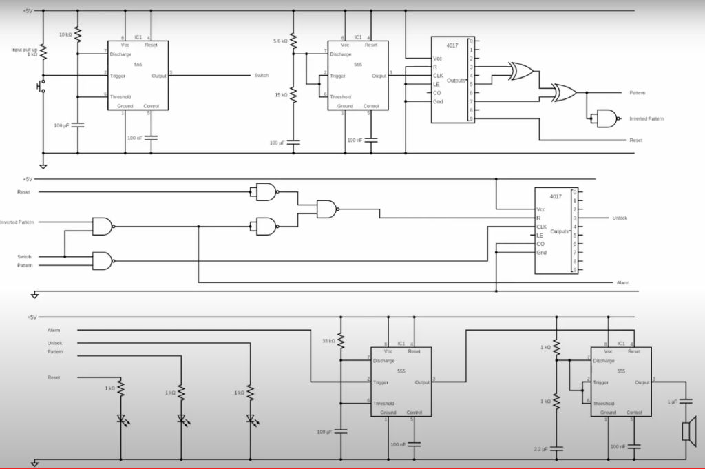
1. The first step for me was to break it up into 5 modules. The modules are input, output, pattern generation, pattern comparison and error detection. By breaking it up into individual self contained modules it makes it easy to build and join each module separately.
2. I designed the pattern generation component first over the input as technically the pattern generation is also technically an input in this case. When the user and the pattern generation are in concert an alarm should sound. The pattern recognition component consists of a 555 timer in astable mode, a binary counter which counts the clock pulses, and a 3 input OR gate built from 6 NAND gates which would be high when any input went high. The pattern generated depended on which counter output the inputs of teh or gate were connected. I chose 3,5, and 7. The pattern generation circuit can be seen in figure 1.
3. I then designed the input, which was a single button with a 555 timer acting asa monostable oscillator. This serves two purposes to debounce the switch and to make switch pulse width wider so that if a user pressed the switch twice in quick succession it would be wider than the a single clock pulse causing the alarm to sound. The design is below.

4. The next step is to build the pattern comparison and error generation circuit. This is quite simple we want to trigger an error in 2 scenarios. The pattern comparison is made quite easily, with a counter that counts when the pattern generation and switch signals are ANDED together and sent to a second BCD counter. This counter is reset if a mistake is made and alarm is triggered.
- The first when a button is pressed when the pattern signal is low.
- The second when only one or two presses are made, the reset is triggered on the 10th clock pulse of the cycle.

5. The final stage is the output. There is a 555 timer that runs in monostable mode which holds the reset of a second 555 timer in astable mode high through an inverter. When the monostable 555 timer goes high when triggered by the alarm signal it enables the astable oscillator which is connected to a speaker. The LEDs make it easy to see the pattern, the switch signal and the reset signal.

Does the electronic lock with pattern recognition work?
See for yourself.

Useful links
https://ohmslawcalculator.com/555-astable-calculator
https://ohmslawcalculator.com/555-monostable-calculator
